My original DIY Megasquirt dashboard was a fun project and has given good service in both my cars over the last couple of years. The wheels of progress are rolling on. With a 50% blowout in cost, I have replaced the 1602 text LCD with a tiny 1.8" $5 TFT colour LCD. This is able to display considerably more information while occupying less space in my dashboard. On the negative side, it's not as easy to read in bright sunlight and programming it was a good deal more complicated.
As before, let's start with photos. Unfortunately, I didn't take any shots along the way, so you only get to see it installed in the dashboard (where the tacho used to be). The photos don't exactly flatter it either -- looks a bit better in the flesh, but I suppose it fighting the camera flash gives you an idea of what it's like in bright sunlight.
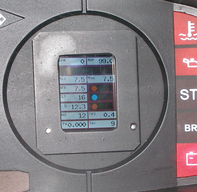
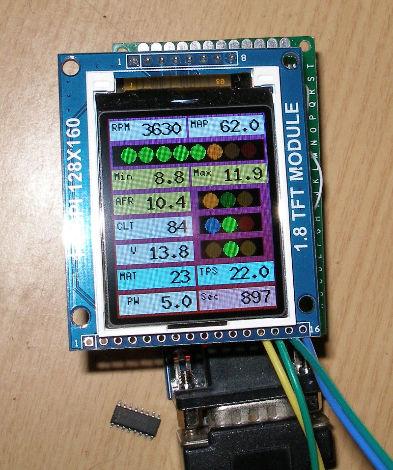
Here's what you're greeted with before starting the engine:
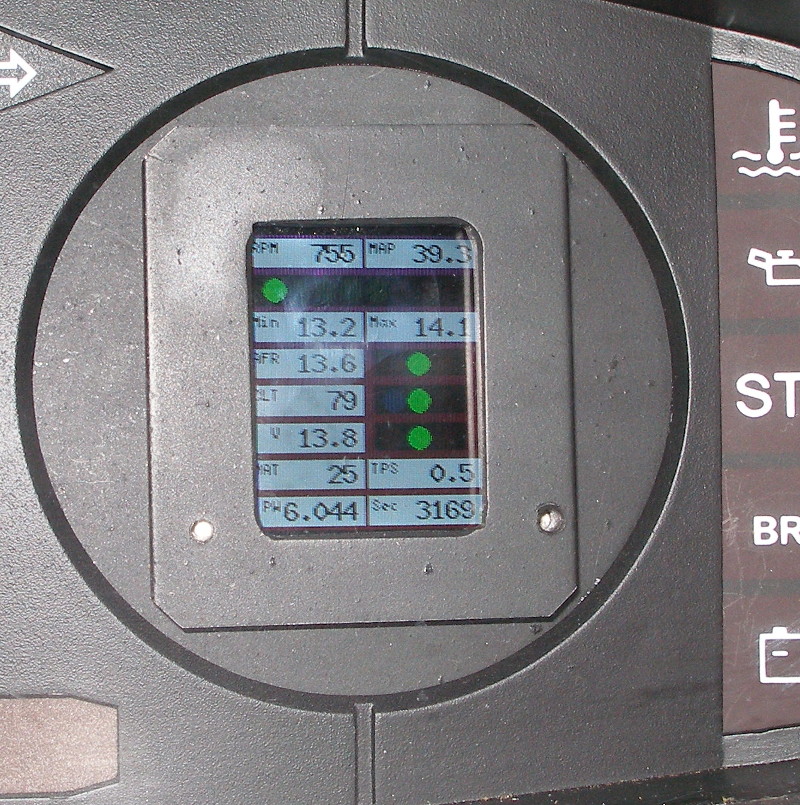
And here it is after it's been running for a while:
As you can see, you can pack quite a lot of information into this small space. It provides a pretty good at-a-glance overall status, with details right there if anything is wrong. I haven't found it too distracting when driving, and it gives you something to look at when waiting at traffic lights.
UPDATE: I built a second board so have added a few more pics. This build replaces the NPN transistor with a PNP as mentioned below. Definitely brighter and does a better job competing with the camera flash. The software is slightly different too, with a new text background colour option.
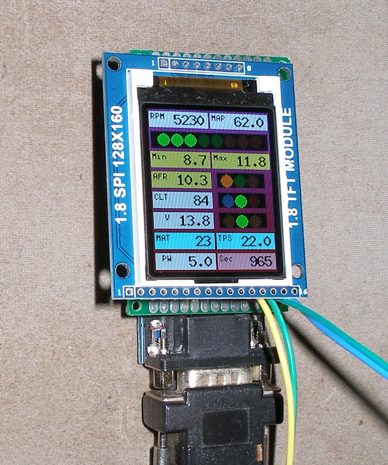
As a bonus the faulty MAX3232 chip made an accidental guest appearance in that second shot.
In case you're wondering about the "inconsistent" LED and RPM readings, it's because one of the photos was taken just after the simulated RPMs wrapped around. The RPM field, being averaged over the previous two seconds, was higher than the LED value. This lag could be avoided by making the RPM text field refer to a last method value instead of a mean.
Hardware description follows, then the software.
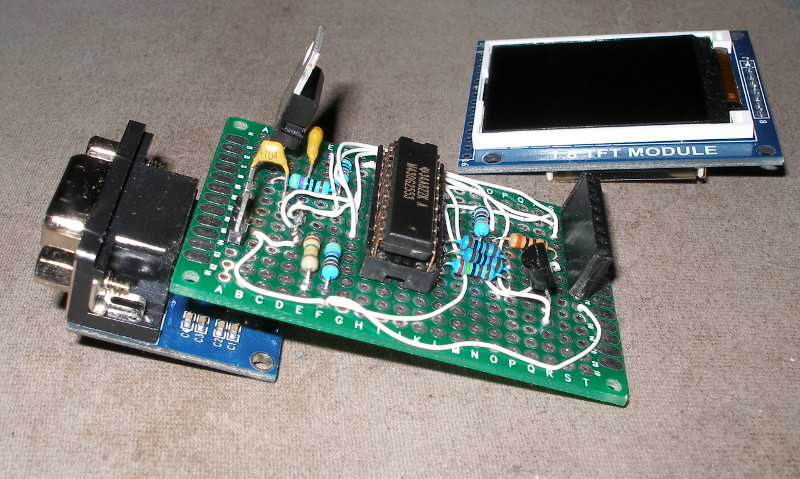
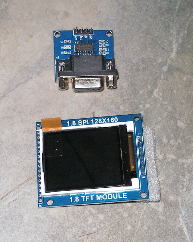
Once again using TI's MSP430G2553 20 pin DIP microcontroller, this time running at 3.3V. RS-232 duties are carried out by a cheap MAX3232 module from eBay. Unfortunately I chose one that was a bit too cheap and had to replace the MAX3232 chip (common problem apparently). Even so it was still good value. The TFT display is based on the ST7735S chip. The 1.8" display area has 128x160 pixels and 18-bit colour.
Here are the modules as bought from eBay:
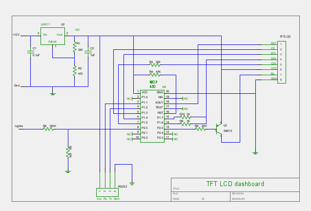
And here is the schematic:
This is obviously a much simpler schematic than the LCD1602 version. That's largely down to using the off-the-shelf RS-232 transceiver, but also because it communicates with the display using the SPI protocol, so only 4 wires. Another simplification is that everything is running at 3.3V, so one regulated power line does for all.
The CPU is running at 12MHz. With the display plugged directly into the circuit board, SPI worked well at the same speed. The board wouldn't fit easily in the instrument cluster and introducing a 15" cable between board and display meant I had to halve the speed of the SPI bus. At that, it's still fast enough.
It was easy to implement the "lights" connection this time. If pin 2.0 goes high, the PWM duty cycle is reduced on pin 2.5. The brightness is software configurable.
In hindsight it would have been wiser to use an S9015 PNP transistor in place of Q1. This would deliver full voltage to the backlight even when the BL pin comes well above ground. It'd be a bit brighter. (UPDATE: Done, and it was. Schematic updated accordingly.)
Mounting this wasn't too bad. I made the bezel thick so I could tap threads for screws coming from the back, and large because the display's circuit board is considerably larger then the display itself. A 3D printer could no doubt provide a better looking result.
As an aside, I'll have to give mid-80s Peugeot an award for the stupidest connector I've come across. I put this gauge in place of the standard tachometer, leaving the old connector taped out of the way. However, unconnected, its spring clip shorts all its terminals together. Brilliant. Only found this out with the burning insulation smell when I started the engine.
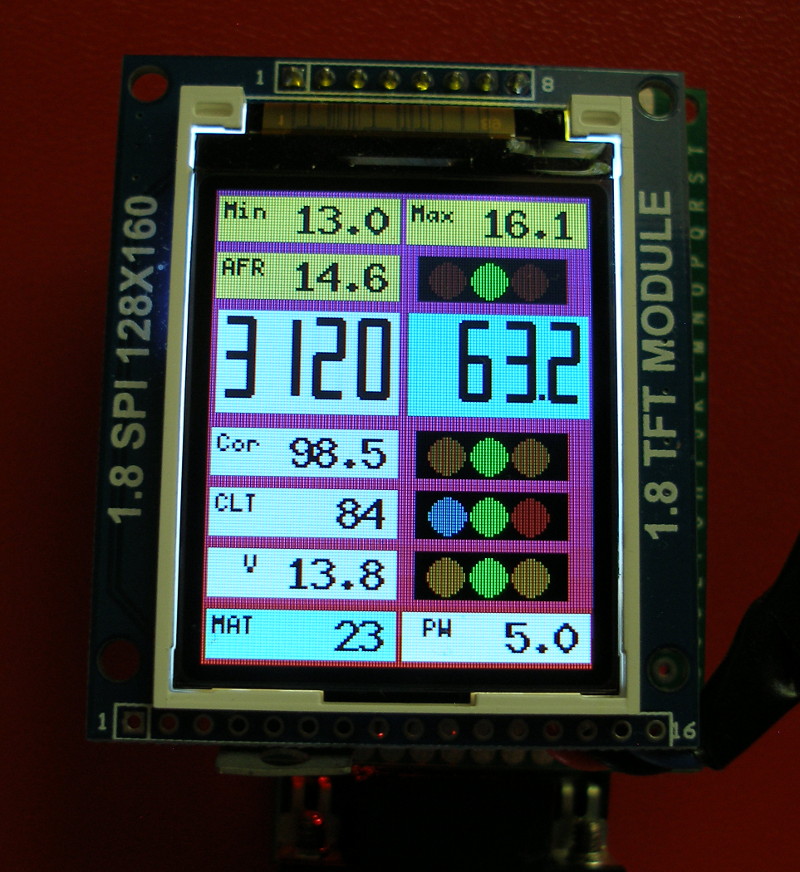
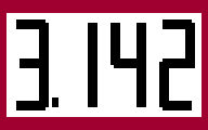
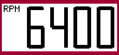
UPDATE 2: Have now added the seg7 widget giving double-height numbers simulating a 4-digit 7 segment display. There is no room for labels, so it's up to you to know what it's telling you.
Here is a photo of my latest configuration, incorporating the new widget for RPM and MAP, with AFR info above, and EGO correction immediately below. RPM uses the last method, so it updates 16 times per second. Everything else updates at a 2 second interval.
The new layout has cost me the ledbar RPM widget, but I found I never looked at it when driving, snazzy though it was when free revving in neutral.
UPDATE 3: Added the ability for the background colour of the seg7 widget to be set according to the range of the number being displayed. Also added the ability for a blank field to display a short label.
UPDATE 4: Added Mseg7 widget and removed Rangebar. This page is behind the times on inverse video and colour selection. Things are more up-to-date in the configuration page.
The software has quite a lot in common with the original dashboard. All the communications with the Megasquirt are the same, as is the RS232 flash update capability.
In brief, the Megasquirt is still polled 16 times per second to send a user-configurable slice of its "OutputChannels". The dashboard accumulates these for 2,4,8,16,32,... samples then updates the values on the display. If the Megasquirt isn't connected to the RS-232 port as a slave, the dashboard looks for a computer talking as master. This allows upgrading the firmware, or the 192 byte configuration flash. If you want further details of those features, read the previous project's blurb.
The following widget types are available:
![]()


| Name | Meaning |
|---|---|
| bg | two 16-bit colour values (5 bits red, 6 bits green, 5 bits blue). The background is a gradient from one to the other. |
| blduty | two 8-bit values in [0:100] defining the day and night PWM duty for the backlight (e.g. 90,30 would give 90% backlight duty by day, 30% duty when the lights are on). |
One other significant change from the previous project is in the method field in the poll specification. Mean, min and max are as before, but last now causes any widget using that value to be refreshed 16 times per second (i.e. every poll rather than the number of polls specified in pollcycle). This is included so that an RPM ledbar can update quickly, but it also works with all the other widgets (at some cost in readability).
Everything's written in MSP430 assembly language. The executable has grown appreciably but is still small. The fixed part, which looks after reflashing via RS-232, is just under 1k, the dashboard code itself is about 4.5k, and there is just under 2k of font data.
As an echo of my time-wasting with the 1602 display, I spent a fair bit of effort making sure I had read/write access to the display. In the end, nothing is being read back from the display. I guess it's nice that my library supports it anyway.
It would be good if the display wasn't quite so small. I did buy a couple of 2.8" 240x320 displays, and I didn't have much bother updating the library to talk to them (biggest hassle was that the 320 pixels were too many to address in 8 bits). But they run slower, and their individual pixels are actually smaller than this display, so you have to send many more pixels to present a larger image. What would be really nice would be to have a 2.5" display that was still only 128x160 pixels.
If you'd like a copy of the source or the schematic file (for gEDA's gschem), or you have some comments, drop me an e-mail at robsproj9@gmail.com or PM me as robs at the MS2/Extra forums. I'd also consider sending pre-programmed MSP430 chips to people who don't mind building the hardware but find the software off-putting.