
The little Megasquirt dashboard was originally intended to let you configure a single screen layout. The software was recently changed to support up to six layouts. To make use of this you need a "next-conf" button. Each press will take you to the next configured layout.
Because a button wasn't in the original design, a small circuit modification (perhaps a bit too small) is needed.
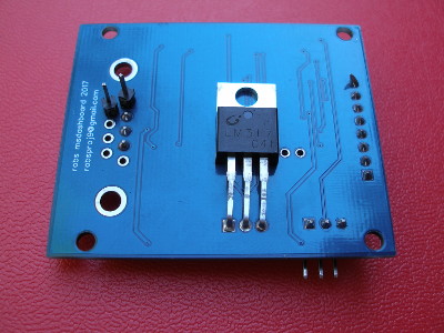
Here are two photos of the modified board:
As you can see, an AWG30 wire has been soldered to pin 10 of the MSP430 (U1). It is then brought to a pin attached to the underside of the board in one of the free RS232 holes. A second pin has been soldered to the hole for pin 5 of the RS232 connector. This hole is already connected to ground. A normally open momentary button across these two pins will let you signal next-conf to the processor. Using pins is preferable to taking wires straight to a button because there is less chance of a wire being tugged and damaging the board and/or processor.
There were a number of processor pins that could have been used. This one was chosen to make the soldering as easy as possible. It is at the end of the processor and the adjacent pin (pin 9) is free, so it won't really matter if you end up with a solder bridge. However, pin 8 is used, so don't get carried away.
Feel free to orient the board whatever way suits you best. I'm right handed and found it easiest with the board about 60 degrees clockwise from the upper photo. Had a drop of solder on the tip of the iron and just held the wire in place by hand (tweezers just made it harder for me). Touching wire and the pad with the soldering iron for a moment did the trick.
Lighting is important and magnification might help. I was able to do this with reading glasses and a good LED light.
For the button to be useful you will need the newer firmware which knows about it and an updated cfg.pm Perl module to allow you to define multiple screen layouts.