Coorong Traveller part 2
Progress report on the building of Duck Flat Wooden Boats "Coorong Traveller"
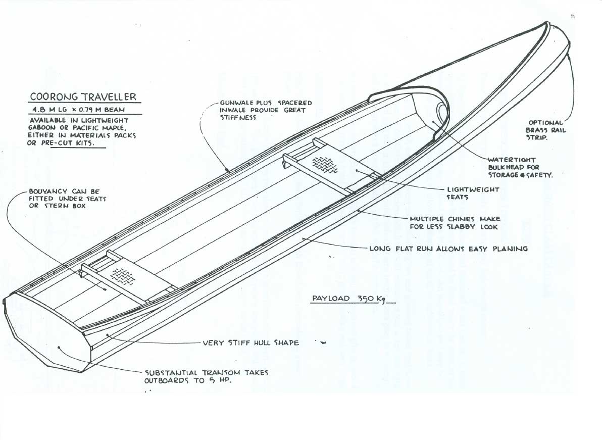
This little boat is just under 16' long, has a canoe stem and a small transom at the stern for outboards up to 5Hp. I will be using a 44lb thrust, 12volt trolling motor with two deep-cycle 12v lead acid batteries in parallel.
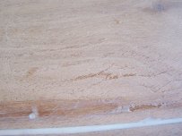
I had mentioned that the ply was not finished very well and that I intended to paint. .......
Here is a closeup of the problem I have on the hull panels.
Remember to click on the image for a much larger view.
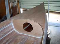
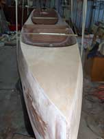
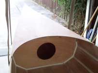
Not a lot appears to have happened, but I have done a lot of sanding and filling to hide the tapes when painted. For a change I thought I would fit the bow deck and seal in the front bouyancy chamber just so it looked like I was doing something. Sealed all the wood first and remembered to fit a brace half way forward and reinforced just back from the bow to take a stainless saddle.
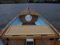
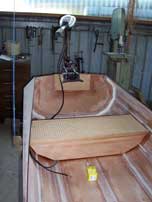
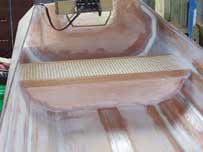
In between sanding I fabricated a rear seat. This will have a cushion made to fit for longer trips while the front passenger will sit on the floor on a foam seat. This will be made and upholstered to sit back against the battery box for support. Seat still has to be fitted (see photo).
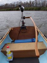
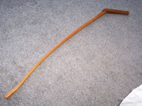
I have also been sketching another tiller for the motor. Something lower and bent to come around my right (or left) side for extended cruising without having to twist my back. Wouldn't have throttle control, but that may come. I have a 20Amp variable throttle circuit built for another project, and will try that if I am not drawing too much current. Could add some big heatsinks which may help. So for now it's back to the sanding and filling and sourcing some nice WRCedar or similar for the outwales and inwales.
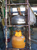
A steamer was made from an old, out of date gas cylinder sat on a single burner gas stove which mounts directly onto a full
gas bottle. A hole was drilled to allow addition of water and a hose fitting directed the steam into a plastic pipe, plugged at one end
with a wooden plug (with water outlet for condensed steam) and stuffed with rags around the wood to be steamed.
The strips are only 10mm x 20mm and about 5M in length. Once soft they were clamped around the hull to dry. It was
then a few months before I got to permanently attach them to the hull. Small 10mm x 20mm x 180mm blocks were cut (with a drill press)
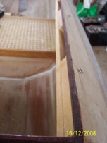
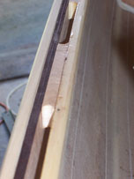
and glued to the inwale strip which was then glued and screwed to the shear. I was concerned about the integrity of the ply as some glue
joints had opened slightly and I could imagine the whole inwale coming off in my hands when trying to lift the boat out of the water!
I can thoroughly recommend Robinson, square-drive stainless screws especially when working alone as they can be placed on the driver
without any worry of them falling off before being driven! The gunwale strip was glued over the screw heads and clamped until set.
Not really happy with the shape of the sheer, but once the clamps were removed it was all just too late! From the plans I
couldn't see how the gunwale could follow the hull near the stern and it needed a real twist and plenty of epoxy to make it happen.
During the Winter when the epoxy was too thick to pump and I was busy anyway, I made a new tiller for the outboard
and built the electronics to control the motor more smoothly. The tiller clamps to the stainless motor shaft on left or right
side as desired. I am also interested in trying to increase the thrust of the motor
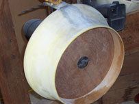
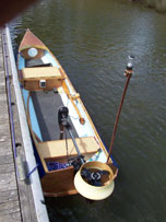
using a nozzle, and decide to try a Rice design rather than a Kort nozzle even though dimensions weren't available. A ply
disk was mounted on the propshaft sized to the diameter of the prop plus 3mm. 1/32" ply was then wrapped around
the disk and closed-cell foam (sleep mat) wrapped and glued around that. The whole lot was then spun in a drill press
and sanded to a shape that I thought looked right. Several coats of epoxy and an aluminium bracket were then added.
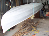
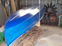
Finally sealed the hull and put on a couople of coats of undercoat and one blue topcoat...rolled and brushed.
Another two or three to go after a light sand between. Just using exterior acrylic gloss house paint as I have heard
one can get good results with care.
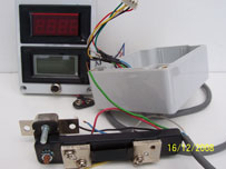
The picture on the left shows the digital volt meter and ammeter with the required shunt across which the voltage drop is measure and current calculated.
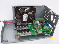
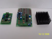
Attached to the shunt in the foreground is a 50A overload cutout. The next two picture are the 1000W speed control circuit with heatsink
and the old computer power supply case used to house it. Don't know if the fan will be needed, but was in the case so there will be a
switch in one of the cutouts on the right to disconnect it as required. The heatsink may be enough as the 360 Watts (about 1/2 HP) this motor should draw.
Speed controller kits were obtained from Oatley Electronics (www.oatleyelectronics.com) and the meters from ebuystufffromanywhere!
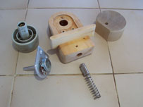
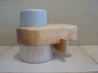
The speed controller requires a 10k potentiometer to control forward and reverse speeds by varying the frequency of the applied voltage. A computer printer drum handle was found which had a flat on the shaft and would accept a bush to fit the shaft of the pot. A stainless pin and spring mate against the handle shaft, and the flat provides positive "neutral" positioning of the control. The completed control can be clipped into the gunnel at the most comfortable position for driver. The boat has now been named the "Miniwatt" (for numerous reasons).
"MINIWATT" IN THE WATER
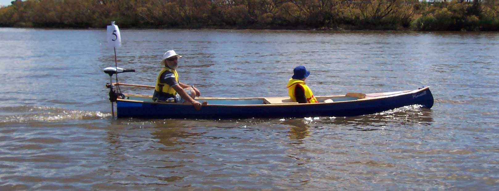
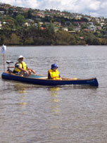
This is the first image of the Coorong Traveller on the water, under power, with two on-board. I took part in an alternative powered boat challenge run by the Australian Maritime College as part of the 2009 Wooden Boat Rally held in Launcston, Tasmania in February. Average speed was 3.2 knotts at 38.5amps. This was a higher current than expected, but the batteries have a total capacity of 210 amps so duration (for my use anyway) won't be a problem.
Feb 25, 2009
Contact the builder: B Kennedy
© 2009 Brent Kennedy
 ..
..
 ..
..
 ..
..
 ..
..